Get Megger Test Form in PDF
Get Megger Test Form in PDF
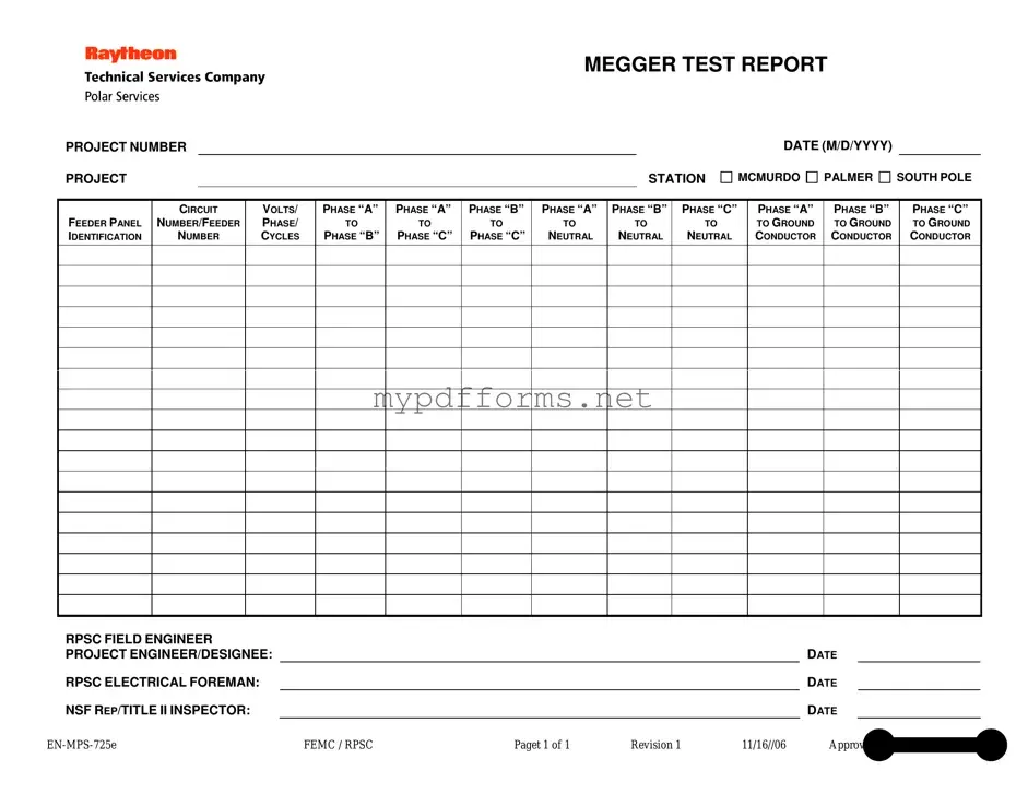
The Megger Test form is an essential document used in electrical testing, particularly for assessing insulation resistance in various electrical systems. This form captures critical information, including the project number, station details, and the date of the test, ensuring that all data is accurately recorded for future reference. It outlines specific parameters such as the feeder panel identification and circuit numbers, which help in identifying the components being tested. Voltage levels across different phases are meticulously documented, including measurements between phases A, B, and C, as well as their respective connections to neutral and ground. The form also requires the signatures of key personnel involved in the testing process, such as the RPSC field engineer and the project engineer or designee, adding a layer of accountability and verification. By providing a structured approach to documenting these test results, the Megger Test form plays a vital role in maintaining safety and compliance within electrical systems.
When filling out the Megger Test form, attention to detail is crucial. Here are six important guidelines to follow:
Kink Checkbox - Finds hairbrush spankings to be a playful form of discipline.
Dd Form 2870 Army Pubs - This form ensures that all requests for medical service are properly documented.
Completing the Illinois Employee Handbook form is essential for fostering a clear understanding of workplace dynamics and ensuring compliance with company policies. For more information and to access the necessary resources, you can visit Illinois Forms, which provides valuable guidance on how to navigate this important aspect of employment.
Dl-43 Form - Submitting the DL-43 form in a timely manner can help avoid penalties associated with expired licenses.
When filling out and using the Megger Test form, keep these key takeaways in mind:
Following these steps will help ensure that the Megger Test form is filled out correctly and used effectively.
Filling out the Megger Test form is a straightforward process. This form is essential for documenting electrical tests conducted at various project sites. Each section requires specific information related to the project and test results. Follow these steps to ensure that all necessary details are accurately captured.
A Megger Test, or insulation resistance test, is a method used to assess the integrity of electrical insulation in various components, such as cables and motors. By applying a high voltage, typically between 250V to 1000V, the test measures the resistance of the insulation. This helps identify potential faults that could lead to electrical failures or safety hazards.
The Megger Test form contains essential details about the test conducted. Key information includes:
All these elements ensure that the test results are accurately recorded and can be referenced in future assessments.
The results from the Megger Test are typically expressed in ohms. Higher resistance values indicate better insulation quality, while lower values may suggest potential issues. Generally, a resistance value above 1 megohm is considered acceptable for most applications, but specific requirements may vary depending on the equipment and industry standards.
The Megger Test should be performed by qualified personnel, such as an electrical engineer or technician with experience in electrical systems. This ensures that the test is conducted safely and accurately. The results must then be reviewed and approved by a designated project engineer or electrical foreman.
If the Megger Test indicates low insulation resistance, immediate action is necessary. The affected equipment should be taken out of service to prevent potential electrical hazards. Further investigation is required to identify the cause of the low readings, which may involve visual inspections or additional testing. Repairs or replacements may be needed based on the findings.
The Electrical Inspection Report is a document that serves a similar purpose to the Megger Test form. It provides a comprehensive overview of the electrical systems within a facility. Like the Megger Test, it includes detailed measurements and assessments of electrical components to ensure they meet safety standards. The report typically highlights any potential issues and suggests necessary repairs or improvements, ensuring that the electrical systems operate safely and efficiently.
The Circuit Analysis Report is another document that shares similarities with the Megger Test form. This report focuses on evaluating the performance of electrical circuits. It includes data on voltage, current, and resistance, much like the Megger Test. Both documents aim to identify any abnormalities in the circuit's performance, helping to prevent electrical failures and ensuring the reliability of the system.
The Insulation Resistance Test Report is closely related to the Megger Test form, as it specifically measures the insulation resistance of electrical components. This report provides critical data on the effectiveness of insulation, which is vital for preventing electrical shocks and equipment damage. Both documents require similar testing procedures and contribute to maintaining electrical safety standards.
The Florida Marriage Application form is an essential document required for couples seeking to obtain a marriage license in the state of Florida. This form captures critical personal information about both individuals, including their names, dates of birth, and residency details. It also includes specific legal stipulations, such as the timeframe within which the marriage must occur and the jurisdictional limitations of the license. For more details, you can visit floridapdfform.com.
The Safety Compliance Checklist is another document that aligns with the objectives of the Megger Test form. This checklist ensures that all electrical installations adhere to safety regulations and standards. While the Megger Test focuses on specific measurements, the checklist provides a broader overview of compliance, including the condition of wiring, grounding, and protective devices.
The Load Testing Report is akin to the Megger Test form in that it evaluates the performance of electrical systems under specific load conditions. This report documents how well a system can handle its rated capacity, similar to how the Megger Test assesses insulation quality. Both reports are essential for ensuring that electrical systems can operate safely under normal and peak conditions.
The Preventive Maintenance Log is another document that shares a connection with the Megger Test form. This log records routine inspections and maintenance performed on electrical systems. It serves as a historical reference, much like the Megger Test report, which documents specific testing results. Both documents are crucial for ensuring ongoing reliability and safety in electrical installations.
The Equipment Calibration Certificate is similar to the Megger Test form in that it verifies the accuracy of testing instruments used in electrical assessments. This certificate ensures that the equipment used for the Megger Test is functioning correctly and provides reliable results. Both documents emphasize the importance of precision in electrical testing and maintenance.
Finally, the Installation Verification Report is related to the Megger Test form as it confirms that electrical installations meet design specifications and safety standards. This report includes various tests and inspections, similar to the Megger Test, to ensure that the installation is safe and functional. Both documents are essential for verifying that electrical systems are installed correctly and can operate safely.
The Megger Test form is essential for documenting electrical insulation resistance tests. However, several other forms and documents are often used alongside it to ensure a comprehensive assessment and compliance with safety standards. Below is a list of related documents that can enhance the testing process.
Using these documents in conjunction with the Megger Test form can help ensure thorough documentation and enhance the safety and reliability of electrical systems. Each form plays a vital role in the overall testing and maintenance process, contributing to compliance and operational efficiency.
The Megger Test is a widely used method for assessing the insulation resistance of electrical systems. However, several misconceptions about this test can lead to confusion. Here are eight common misunderstandings:
By addressing these misconceptions, individuals can gain a clearer understanding of the Megger Test and its importance in maintaining electrical safety and reliability.